
Deixe um recado
Se você estiver interessado em nossos produtos e quiser saber mais detalhes, deixe uma mensagem aqui e responderemos assim que possível.
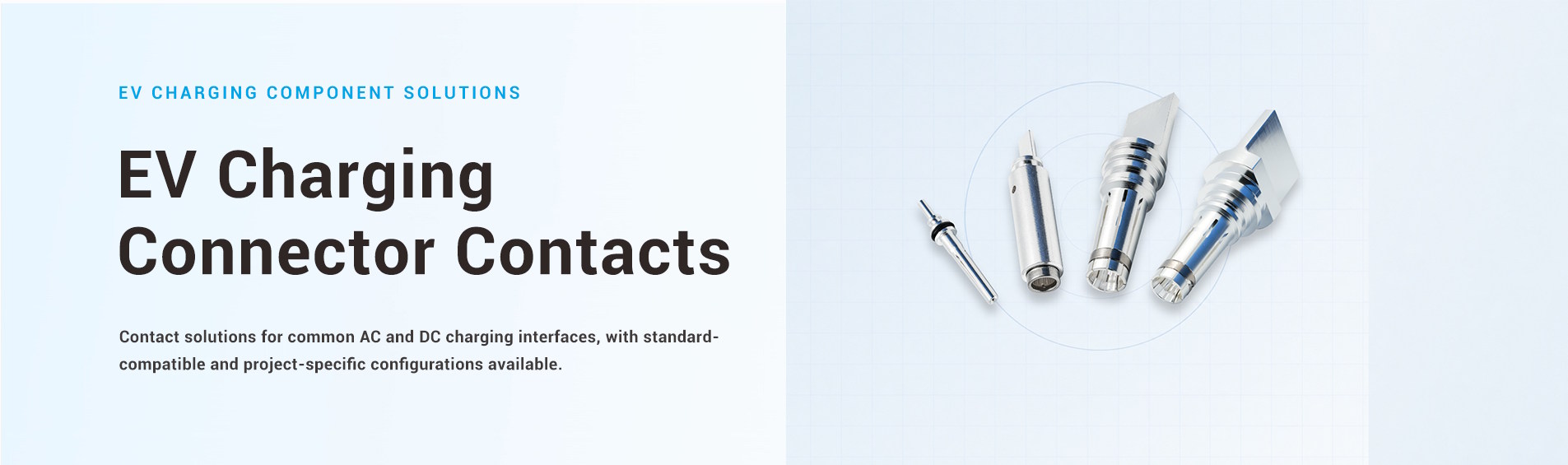
Contatos do conector de carregamento de veículos elétricos
Pinos de contato independentes e contatos de soquete para desenvolvimento e produção de conectores de carregamento de veículos elétricos.
Os contatos do conector de carregamento de veículos elétricos fornecem a interface condutora de acoplamento dentro do conector. Sua geometria, material, acabamento superficial, força de contato e terminação do cabo afetam a forma como a corrente ou os sinais passam pelo conector e como as partes de acoplamento se encaixam.
A Workersbee fornece pinos de contato e contatos de soquete personalizados como componentes independentes para fabricantes de conectores de veículos elétricos e OEMs de equipamentos de carregamento. Fabricamos contatos de alimentação, aterramento de proteção e sinal em configurações macho e fêmea.
Oferecemos suporte ao desenvolvimento personalizado a partir de um desenho, amostra física ou conector existente. Usinagem de precisão, produção de estruturas de contato, amostragem e verificação em nível de conector podem ser incluídas no mesmo fluxo de trabalho do projeto.
Um conector de carregamento de veículo elétrico contém vários contatos com diferentes funções. Os contatos de alimentação, de maior porte, conduzem a corrente de carregamento. O contato de proteção contra sobreaquecimento (PE) fornece o caminho de aterramento, enquanto os contatos de sinal menores suportam funções de controle, proximidade ou comunicação, dependendo da interface do conector.
Esses contatos não podem ser tratados como versões em escala reduzida do mesmo componente. Um contato de alimentação é limitado principalmente pelo seu percurso elétrico e térmico, enquanto um contato de sinal pode priorizar uma conexão estável, geometria compacta e condição da superfície. A carcaça do conector, o condutor do cabo e o contato de acoplamento também influenciam o projeto final.
Função de contato | Função no conector | Principais considerações de projeto |
Contato de energia | Transporta corrente de carregamento CA ou CC | Seção transversal condutiva, resistência de contato, elevação de temperatura, força de contato e terminação do cabo |
Contato PE | Fornece o caminho de aterramento protetor | Continuidade, sequência de acasalamento, retenção e estabilidade mecânica |
Contato de sinal | Suporta funções de controle, proximidade ou comunicação. | Estabilidade de contato, ajuste dimensional, acabamento superficial e durabilidade de acoplamento |
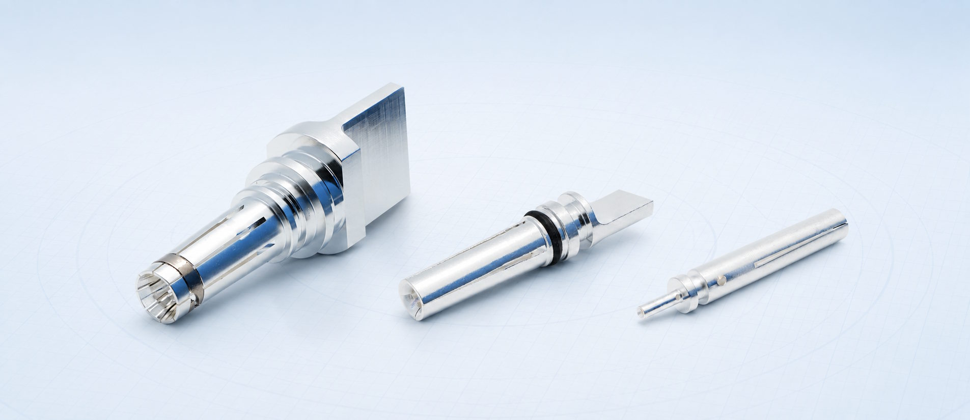
Podemos fabricar pinos macho sólidos, contatos fêmea e contatos auxiliares menores para essas diferentes posições. As dimensões e funções finais são confirmadas de acordo com o projeto do conector e a peça de acoplamento do cliente.
O formato visível de um contato é apenas uma parte do seu projeto. A interface de acoplamento determina como a força de contato é gerada e distribuída, enquanto a seção traseira deve se conectar ao condutor e encaixar-se dentro do conjunto do conector.
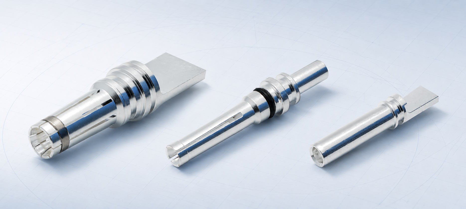
Oferecemos suporte a estruturas de contato sólidas, ranhuradas, com mola de coroa, lamelares e hiperboloides. Também podemos desenvolver componentes de contato para projetos de conectores com refrigeração líquida, adaptados à arquitetura de conector e refrigeração necessária.
Design de contato | Construção básica | Fatores do projeto a confirmar |
contato de pino sólido | Contato macho usinado com uma superfície de acoplamento definida | Diâmetro, comprimento de acoplamento efetivo, acabamento, características de retenção e terminação traseira |
Contato de soquete ranhurado | O contato da fêmea com segmentos elásticos engata no pino de acasalamento | Geometria da ranhura, força de contato, força de inserção, espessura da parede e comportamento de fadiga. |
Contato da mola da coroa | O elemento de mola cria múltiplos pontos de contato ao redor da superfície de acoplamento. | Geometria da mola, método de montagem, força de contato, trajetória da corrente e espaço disponível |
Contato lamelar | Múltiplas venezianas moldadas proporcionam pontos de contato distribuídos. | Geometria da tira, projeto do suporte, diâmetro de acoplamento, força e requisitos térmicos |
contato hiperboloide | Os fios de mola angulados formam múltiplas linhas de contato ao redor do pino de acoplamento. | Disposição dos fios, força de inserção, estabilidade do contato e dimensões de montagem. |
Contato refrigerado a líquido | A geometria de contato é desenvolvida como parte de um conjunto de conectores refrigerados. | Interface de refrigeração, vedação, conexão do condutor, caminho térmico e encapsulamento do conector |
Estruturas de mola coroada, lamelas e hiperboloides podem ser produzidas internamente. A estrutura apropriada depende da geometria de acoplamento e das condições do projeto; a seleção não se baseia apenas na corrente nominal.
Desenvolvemos pinos de contato e contatos de soquete para projetos de conectores Tipo 1, Tipo 2, CCS1, CCS2, GB/T e NACS. Essas interfaces incluem diferentes combinações de contatos de alimentação CA ou CC, PE e sinal, portanto, o conjunto de contatos deve seguir o layout do conector e a geometria de acoplamento aplicáveis.
Também é possível desenvolver contatos relacionados ao CHAdeMO e ao MCS para atender a requisitos específicos de projetos. Nesses casos, os contatos são tratados como projetos personalizados, e não como faixas de contato padrão.
A abrangência da interface não significa que um projeto de contato possa ser transferido sem alterações entre normas. Mesmo contatos com funções semelhantes podem diferir em dimensões de acoplamento, retenção, vedação, conexão do condutor e condições térmicas.
Assim, analisamos o desenho, a amostra ou o conector de acoplamento antes de confirmar a viabilidade de fabricação e o plano de validação.
A corrente elétrica percorre a terminação do condutor, o corpo de contato e a interface de acoplamento. A resistência em qualquer um desses pontos gera calor, portanto, o projeto deve ser avaliado considerando todo o percurso da corrente, e não apenas a condutividade do material base.
A seção transversal de contato, a pressão de acoplamento, a condição da superfície, o revestimento, a conexão do condutor e o ajuste da montagem podem influenciar a resistência de contato e o aumento da temperatura.
Projetos de alta corrente também podem exigir que o design do contato acomode a arquitetura de detecção de temperatura ou de resfriamento líquido do conector. Essas interfaces são confirmadas durante a integração do conector, em vez de serem presumidas a partir do formato do contato.
O contato deve entrar na peça de acoplamento sem força excessiva, mantendo pressão suficiente após a conexão. A geometria da ranhura, da mola ou da lamela afeta tanto a força de inserção quanto a estabilidade da interface elétrica.
Os elementos de retenção e as vedações também devem manter o contato na posição pretendida dentro da carcaça. Ranhuras, ressaltos, anéis de vedação e a geometria da extremidade traseira são, portanto, partes funcionais da montagem, e não detalhes de usinagem meramente estéticos.
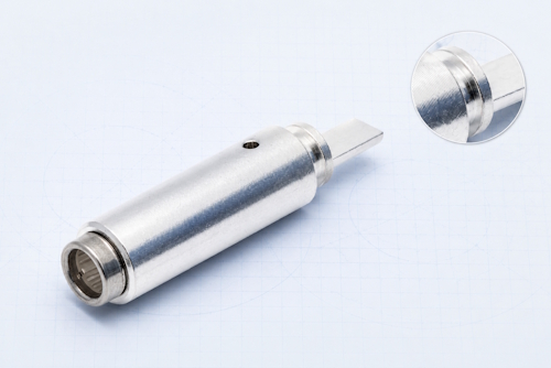
Fabricamos contatos em cobre e ligas de cobre selecionadas de acordo com o desenho, os requisitos elétricos, o comportamento mecânico e o processo de produção.
Os acabamentos cromados disponíveis incluem:
· Banhado a prata
· Estanhado
· Niquelado
O revestimento é realizado por parceiros de processamento externos. As especificações de acabamento e os requisitos de inspeção são confirmados como parte da documentação do projeto.
A parte traseira do contato deve ser compatível com o condutor e o processo de montagem do conector. Oferecemos suporte a interfaces planas para soldagem ultrassônica, bem como extremidades de soldagem redondas.
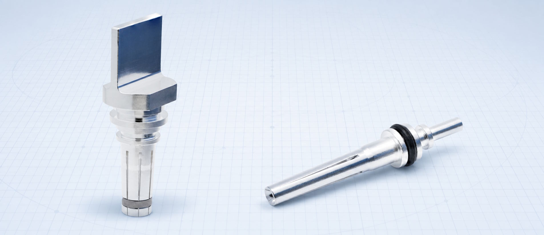
Recortes usinados, ranhuras, sulcos de vedação e outros recursos de montagem podem ser integrados onde a estrutura do conector exigir.
A terminação não pode ser definida apenas com base na bitola do cabo. É necessário considerar em conjunto a construção do condutor, o espaço disponível para a montagem, o processo de junção, os requisitos de tração e o caminho térmico.
Um projeto de contato pode começar com um desenho completo, uma amostra física de contato ou um conector existente que necessite de um componente correspondente.
Também podemos auxiliar no projeto de contato quando os requisitos do conector e de acoplamento estiverem definidos, mas o desenho do contato ainda não estiver concluído.
O caminho normal de desenvolvimento é:
1. Analise a referência disponível.
Analisamos o desenho, a amostra, a interface do conector ou o componente de acoplamento e identificamos a função do contato.
2. Confirme as interfaces críticas.
São definidas as dimensões de acoplamento, retenção, vedação, conexão do condutor e espaço de montagem disponível.
3. Alinhar as decisões de materiais e de fabricação
A estrutura de contato, o material de cobre ou liga de cobre, o revestimento, o processo de usinagem e os processos secundários foram confirmados.
4. Produzir e inspecionar amostras
Os contatos do protótipo são verificados em relação às dimensões acordadas e montados com as peças de conexão relevantes quando necessário.
5. Verifique a interface do conector.
Os testes elétricos, mecânicos e de elevação de temperatura são selecionados de acordo com o projeto antes que os requisitos de produção sejam finalizados.
Após a aprovação da amostra, o desenho confirmado, o processo de fabricação e os requisitos de inspeção podem ser transferidos para a produção em lote.
Para uma análise inicial, os clientes não precisam preparar um pacote de validação completo. Um desenho, uma amostra física ou um conector existente, juntamente com a função de contato e a conexão pretendida do condutor, geralmente são suficientes para iniciar a discussão técnica.
Os contatos dos conectores de veículos elétricos frequentemente combinam superfícies torneadas, detalhes internos profundos, ranhuras, fendas, furos transversais e geometria de conexão traseira em uma peça compacta. Manter a relação entre esses elementos é importante para o acoplamento, a vedação e a montagem.
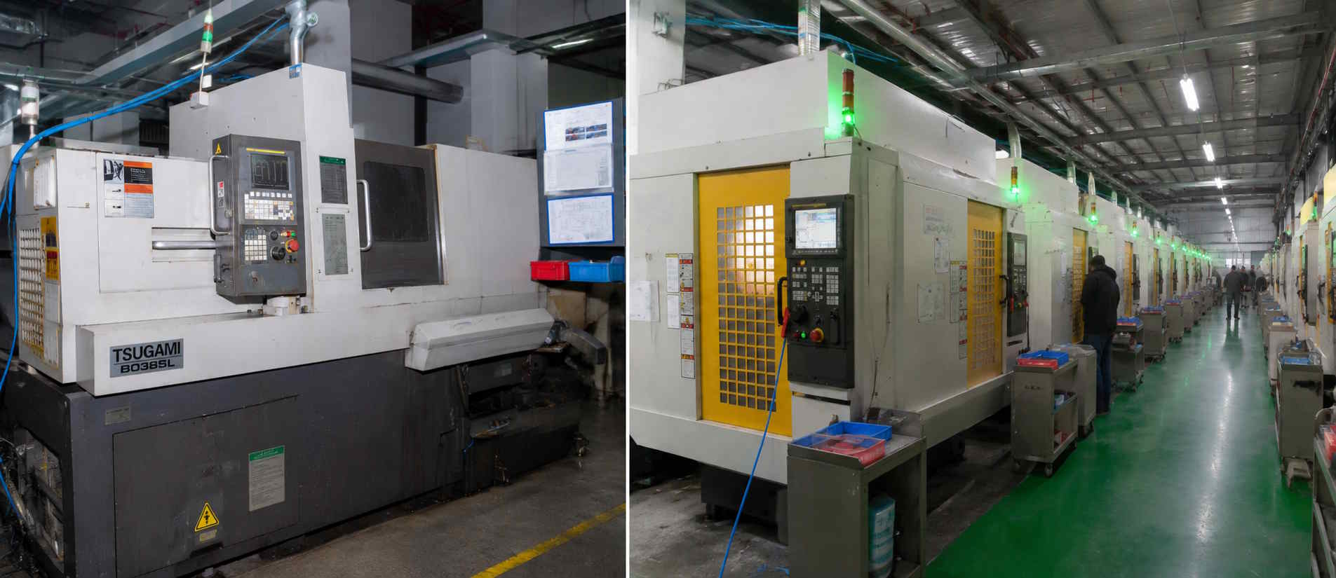
Nossa operação de fabricação de precisão inclui 66 tornos CNC tipo suíço e 27 centros de usinagem FANUC em duas bases de produção.
Dependendo da peça, torneamento, fresagem, furação e ranhuramento podem ser combinados em uma única sequência de usinagem, incluindo o trabalho nos fusos principal e secundário. Estampagem e conformação também estão disponíveis para elementos de contato de molas e lamelas.
Os processos de suporte incluem:
· Rebarbação
· Acabamento magnético e vibratório
· Jateamento de areia
· Limpeza ultrassônica
· Galvanoplastia externa e tratamento de superfície
A rota de produção é selecionada de acordo com a geometria de contato, os requisitos da amostra e o volume esperado, em vez de aplicar o mesmo processo a todos os componentes.
A Workersbee opera sistemas de gestão da qualidade certificados pelas normas ISO 9001 e IATF 16949. Essas são certificações de sistemas de fabricação em nível corporativo. As normas aplicáveis aos conectores e quaisquer requisitos de conformidade em nível de produto ainda precisam ser analisados para cada projeto específico.
A inspeção de peças começa com as dimensões e características que controlam a montagem e o acoplamento. Dependendo do desenho, isso pode incluir:
· Diâmetros externo e interno
· Comprimento total
· Sulcos e ombros
· Vagas e oportunidades
· Concentricidade
· Condições da superfície
· Espessura do revestimento
Nossos recursos de inspeção incluem máquinas de medição por vídeo, medidores de rugosidade superficial, medidores de espessura de revestimento, microscópios e equipamentos automáticos de inspeção e classificação dimensional.
A inspeção automática pode ser aplicada a características como diâmetro interno e comprimento total, quando adequada para a peça em produção.
Além da inspeção dimensional, oferecemos suporte rotineiro a:
· Teste de resistência de contato
· Testes de força de inserção e retirada
· Teste de retenção de contato
· Teste de arrancamento do condutor
· Teste de aumento de temperatura
· Verificação da montagem e encaixe do conector
A combinação de testes e os critérios de aceitação são acordados para o contato e conector específicos.
Um contato pode passar pela inspeção dimensional e ainda assim necessitar de ajustes após o acoplamento ou avaliação do aumento de temperatura. Portanto, a verificação em nível de conector é incluída quando exigida pelo projeto.
O ponto de partida mais útil é um dos seguintes:
· Um desenho de contato em 2D ou 3D
· Uma amostra de contato físico
· Um conector de carregamento existente e sua peça de acoplamento.
Por favor, identifique também a interface do conector, se o contato é usado para alimentação, PE ou sinalização, e como ele se conecta ao condutor.
A quantidade de amostras desejada e a demanda de produção esperada nos ajudam a planejar a rota de fabricação, mas não são requisitos para iniciar a primeira análise técnica.
A qualidade do material, os requisitos de revestimento, as condições elétricas, os requisitos de força mecânica, os detalhes de vedação e os critérios de validação podem então ser confirmados com nossa equipe de engenharia à medida que o projeto avança.
Sim. Um projeto pode começar com um desenho, uma amostra física ou um conector existente. Analisamos a geometria de acoplamento, a função de contato, a retenção, a terminação e o espaço de montagem antes de confirmar o processo de fabricação e validação.
Sim. Fabricamos pinos macho, soquetes fêmea e contatos auxiliares menores para alimentação, PE e sinais.
As estruturas disponíveis incluem contatos sólidos, ranhurados, de mola coroa, lamelares e hiperboloides, bem como contatos desenvolvidos para projetos de conectores refrigerados a líquido.
A cobertura regular inclui os tipos 1 e 2, CCS1, CCS2, GB/T e NACS. Os contatos relacionados ao CHAdeMO e ao MCS são tratados conforme o desenvolvimento específico de cada projeto.
Os contatos podem ser fabricados em cobre e ligas de cobre, de acordo com o desenho e a aplicação. Estão disponíveis acabamentos prateados, estanhados e niquelados. Os requisitos de material base e acabamento são definidos para cada projeto.
Oferecemos suporte a terminais de contato planos projetados para soldagem ultrassônica e terminais de soldagem circulares. Outras características de retenção, vedação e montagem podem ser consultadas no projeto do conector.
Sim. É possível produzir amostras para inspeção dimensional, montagem de conectores e para os testes elétricos, mecânicos ou de elevação de temperatura acordados, antes da definição final dos requisitos de produção.
Sim. Assim que a amostra for aprovada e o desenho, o processo de fabricação e os requisitos de inspeção forem confirmados, o contrato poderá iniciar a produção em lote de acordo com os requisitos do projeto acordados.
Rotineiramente, oferecemos suporte para inspeção dimensional, resistência de contato, força de inserção e retirada, força de retenção, extração do condutor, elevação de temperatura e verificação de montagem e encaixe do conector.
Os métodos aplicáveis e os critérios de aceitação são definidos para cada projeto individual.
Deixe um recado
Digitalizar para Wechat :

Digitalizar para WhatsApp :





 Português